Floating Elegance: Decoding the Design of a Mono Stringer Beam Staircase

A mono stringer staircase, also known as a single stringer staircase, is a type of staircase characterized by having its treads supported by a single, central beam or "stringer."
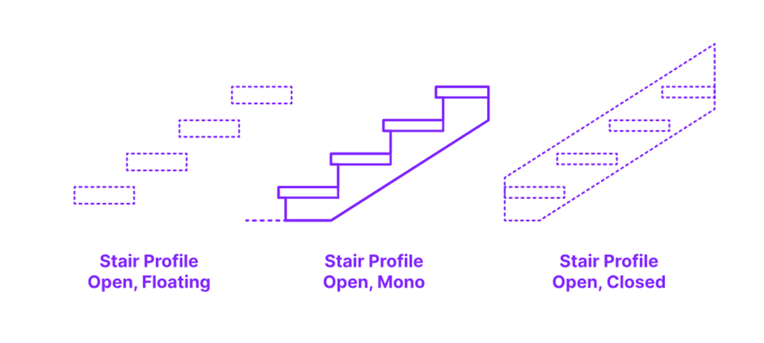
This stringer typically runs down the center of the staircase, underneath the treads, creating a visually open and minimalist design.
Here are the key features that define a mono stringer staircase:
- Single Central Support: The defining characteristic is the single, central stringer. This is in contrast to traditional staircases that have two stringers, one on each side.
- Open and Airy Aesthetic: The absence of side stringers allows for a more open and less obstructed view around the staircase. This creates a sense of lightness and "floating" treads.
- Modern and Minimalist Style: Mono stringer staircases are strongly associated with contemporary and minimalist architectural styles due to their clean lines and reduced visual bulk.
- Structural Focus: The central stringer is a critical structural element, often made of steel or reinforced concrete to provide the necessary support for the entire staircase.
- Variety of Materials: While the stringer is typically metal or concrete, the treads can be made from various materials like wood, glass, stone, or metal, allowing for design flexibility.
In essence, a mono stringer staircase is a design choice that prioritizes visual simplicity and a modern aesthetic by making the central structural support the primary, and often only, visible support for the treads.
Dimensions & Sizes-
Open Mono Stair Profiles are constructed with typical stair tread thicknesses between 1.5”-4” (3.8-10.2 cm) and allowable nosing overlaps of 1”-1.5” (2.5-3.8 cm).
Stair Tread & Riser Sizes
Stair treads have a minimum allowable
depth of 11” (28 cm) with riser heights between 4”-7” (10-18 cm). Stair nosings
can protrude between 1”-1.5” (2.5-3.8 cm) with a maximum riser angle of 30
degrees.


Structural Details -

Project Information:
- Project Name: pkn
- Design: Staircase with Central Stringer Beam
Space and Dimensions:
- Space Available for Staircase: 5.20 m x 4.40 m
- Vertical Distance of Floor (Floor Height): 3600 mm (3.60 m)
- Width of Staircase: 1.40 m (1400 mm)
Staircase Geometry:
- Risers: 0.16 m (160 mm)
- Treads: 0.25 m (250 mm)
- Waist Slab Thickness: 80 mm
Loads and Materials:
- Live Load: 4000 N/m²
- Concrete Grade: M-20 (20 N/mm²) (Note: Image mentions M-25000 which seems to be a typo and likely refers to M-20 or M-25. M-20 is assumed based on typical practice.)
- Concrete Weight: 25000 N/m³ (This is standard unit weight of reinforced concrete)
- Steel Grade: Fy 415 N/mm²
- Nominal Cover: 25 mm
- Effective Cover: 30 mm
Stringer Beam Details (Assumed):
- Assumed Width of Stringer Beam: 200 mm
Reinforcement Details:
Stringer Beam Reinforcement:
- Main Bars: 20 mm diameter, 4 Nos.
- Anchor Bars: 10 mm diameter, 2 Nos.
- Stirrups: 10 mm diameter, 2-legged
- Spacing: 90 mm c/c (at supports/ends - L-section shows '90 mm các' which likely means '90 mm each' or '90 mm spacing')
Waist Slab Reinforcement:
- Waist Slab Bars: 10 mm diameter
- Spacing: 250 mm c/c
Landing Slab Reinforcement (Inferred from Diagram):
- Bottom of Waist Slab Bars: 10 mm diameter @ 250 mm c/c
- Landing Slab Bars (Top): 10 mm diameter @ 300 mm c/c (inferred from L-section near landing)
Diagram Description for Recreation:
1. L-Section (Longitudinal Section):
- Overall Shape: Shows the staircase in profile, including the inclined waist slab and horizontal landing slab.
- Dimensions (Approximate from image):
- Horizontal spans marked as 1.50m, 2.25m, and 1.45m (likely representing different segments of the staircase run).
- Vertical riser height marked as 160 mm.
- Landing slab thickness marked as 80 mm.
- Stringer beam depth is not explicitly dimensioned but can be inferred from the cross-section and L-section view.
- Reinforcement Placement:
- Stringer Beam: Main bars (4-20mm) shown at the bottom of the stringer beam. Anchor bars (2-10mm) shown at the top corners of the stringer beam. Stirrups (10mm diameter, 2-legged) are shown vertically within the stringer beam, with varying spacing:
- 90 mm c/c near the supports/ends of the inclined and landing segments.
- 180 mm c/c in the mid-span of the inclined segment.
- Waist Slab: Waist slab bars (10mm @ 250 mm c/c) are shown running along the length of the waist slab, likely placed at the bottom of the slab (tension side).
- Landing Slab: Bottom reinforcement (10mm @ 250mm c/c) continuous from waist slab. Top reinforcement (10mm @ 300mm c/c) shown in the landing slab.
- Anchor Bars: 10mm anchor bars are shown extending from the stringer beam into the supporting structure at both ends of the staircase.
- Stringer Beam: Main bars (4-20mm) shown at the bottom of the stringer beam. Anchor bars (2-10mm) shown at the top corners of the stringer beam. Stirrups (10mm diameter, 2-legged) are shown vertically within the stringer beam, with varying spacing:
2. Cross-Section at Mid-Span:
- Shape: Shows a cross-section through the waist slab and stringer beam, perpendicular to the staircase run.
- Dimensions:
- Stringer beam width: 200 mm (assumed)
- Waist slab thickness: 80 mm
- Staircase width: 1450 mm (likely the clear width between stringers if there are two, or total width if mono-stringer, though 'width of stair case' is given as 1400mm elsewhere - needs clarification).
- Reinforcement Placement:
- Stringer Beam: Main bars (4-20mm) at the bottom, Anchor bars (2-10mm) at the top corners. Stirrups (10mm diameter, 2-legged) enclosing the main and anchor bars.
- Waist Slab: Waist slab bars (10mm @ 250mm c/c) shown extending outwards from the stringer beam within the waist slab.

Source-
1. Dimension.com
2. Civil Adda
.png)

Comments
Post a Comment